Introduction to Inverting Operational Amplifier
An operational amplifier (op-amp) is a high-gain, multi-stage differential amplifier with two input terminals and one output terminal. It is commonly used in two configurations: inverting and non-inverting. The non-inverting input is denoted by a (+) symbol, while the inverting input is marked with a (-) symbol, representing the positive and negative terminals, respectively. This article provides an overview of the inverting op-amp, explaining its functionality and highlighting its applications.
What is inverting Op-Amp?
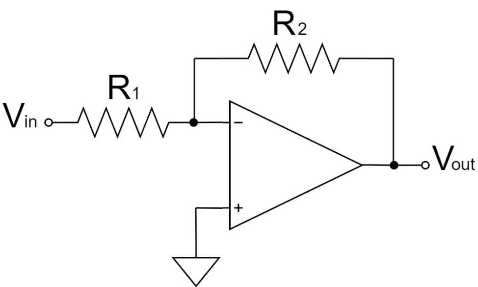
Figure 1. Inverting Op-Amp diagram.
The inverting operational amplifier (op-amp) is a fundamental circuit configuration that utilizes negative feedback to regulate its performance. As the name implies, this amplifier reverses the phase of the input signal while amplifying it.
It is an operational amplifier circuit that produces an output 180 degrees out of phase with its input. This means that when the input signal is positive (+), the output signal is negative (-), and vice versa. The circuit is constructed using an op-amp with two resistors, which determine the gain and feedback characteristics.
How does Inverting Op-Amp Work?
The inverting operational amplifier (op-amp) produces an output signal that is 180° out of phase with the input. The voltage gain is determined by the ratio of two resistors.
Key Equation
The voltage gain \( A_v \) for an inverting op-amp is given by:
Explanation
Where:
- \( V_{\text{out}} \) is the output voltage
- \( V_{\text{in}} \) is the input voltage
- \( R_2 \) is the feedback resistor
- \( R_{\text{1}} \) is the input resistor
The negative sign indicates a phase inversion of 180°.
Virtual Ground Concept
By applying Kirchhoff’s Current Law (KCL) at the inverting node:
This confirms the voltage gain equation.
Conclusion
Using these principles, we can design inverting amplifiers with precise gain values by selecting appropriate resistor ratios.
Resistors Description
R2 is a feedback resistor.
R1 is a resistor connected to \( V_{\text{in}} \).
Start Tutorial