Introduction to RC Charging Circuit
An RC charging circuit is a fundamental electrical circuit that combines a resistor (R) and a capacitor (C) to study the time-dependent behavior of voltage and current. These circuits are widely used in electronics for signal processing, filtering, timing, and energy storage applications.
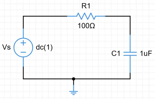
When a capacitor is connected in series with a resistor to a voltage source, the capacitor begins to charge through the resistor. The charging process is not instantaneous but follows an exponential curve, governed by the equation:
VC(t) = Vmax(1 - e-t/RC)
VC(t) is the voltage across the capacitor at time t,
Vmax is the supply voltage,
R is the resistance,
C is the capacitance,
RC is the time constant, which determines the rate of charging.
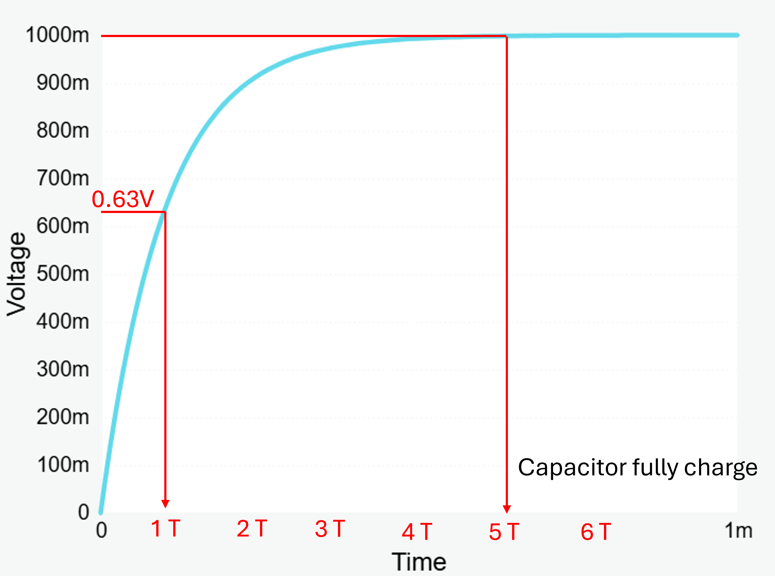
The capacitor (C) charges at a rate depicted by the graph. Initially, the RC charging curve rises steeply because the charging rate is fastest at the beginning. However, this rate decreases exponentially as the capacitor accumulates charge at a progressively slower pace.
As the capacitor charges, the potential difference across its plates increases. The time required for the capacitor to reach 63% of its maximum possible fully charged voltage (0.63Vs in our graph) is referred to as one full Time Constant (T).
The time constant (τ = RC) is a critical parameter in RC circuits, representing the time it takes for the capacitor to charge approximately 63% of the total voltage or discharge to 37% of its initial voltage.
The study of RC charging circuits provides insights into:
- Energy storage and dissipation: Capacitors store energy in an electric field, and resistors control the rate of energy flow.
- Dynamic response: Understanding transient behavior is essential for designing circuits in real-world applications, such as signal processing, clocks, and delay circuits.
By analyzing the RC charging circuit, students and engineers can grasp essential principles of electrical engineering, including transient analysis, exponential behavior, and the interplay between passive components in a circuit.
Start Tutorial